10 Factors That Impact the Injection Mold Cost
How to Overcome Design Concerns for Injection Molded Components
Plastic injection molding is the most versatile method for manufacturing components and products – but this process is complex and peppered with potential pitfalls. Luckily, these issues can be resolved with a highly competent design!
Achieving the best design the first time around is crucial as there is a lot at stake! If OEMs do not get the design right, product rejection rates will increase, productivity will decline, and a host of other issues will ensue – all negatively impacting the bottom line. Additionally, modifying a product or mold design during the production stage can be very costly – so it is worth the time to get the design phase right.
There are many factors to consider when designing a plastic injection molded part. Below are some key decisions made during the design step – that if not made wisely could lead to significant production challenges. This is not a comprehensive list but these are some of the most common design concerns.

Wall Thickness
Simply put, uniform wall thickness is best. Inconsistent wall thickness increases the risk of mold defects such as warping, sink marks, and flow lines.
As the part cools, the thin sections cool first. As the thicker sections cool and shrink, stresses occur between the thin and thick walls. The thinner section does not yield since it has already hardened, resulting in warping, cracking, or twisting. Additionally, flow lines, which are streaks or patterns in the plastic, as well as sink marks, which are small depressions on the part, may appear due to the differential cooling rates.
If uniform wall thickness cannot be achieved, there are ways to overcome this design concern. The change in thickness should be as gradual and smooth as possible with the thicker features being closest to where the molten plastic passes through the gate and into the mold cavity. Use of a fillet or chamfer should also be considered to help ensure the material flows evenly and fills the entire cavity. Additionally, coring is a technique where plastic material is removed from the thicker sections, keeping the overall wall thickness more uniform. There are also process changes that may minimize the impact of uneven wall thickness; for example, operating temperature can be increased to ensure the plastic does not cool too quickly in the thinner sections. In addition, the plastic injection speed can be raised to help the mold fill more uniformly.
As a general rule of thumb, the minimum wall thickness is typically 0.5 - 1 mm and the maximum is around 4 – 5 mm for most injection molding processes; however, the actual wall thickness range will depend on the size of the part and the specific raw material being utilized as not all plastic behaves the same.
Reinforcing Ribs
Continuing with the topic of wall thickness, designers often want to increase the thickness in order to improve product strength. However, as previously discussed, uneven wall thickness can result in a myriad of production issues and product defects. The addition of reinforcing ribs oriented in the direction of the part’s bending forces is a better option. These ribs improve strength and rigidity of thin sections, and avoid distortion of the part.
Generally speaking, rib thickness at the rib base should be around 60% or less of the wall thickness and rib height no more than 3 times the wall thickness.
Corners
When it comes to corners or edges, smooth is best. Sharp corners add stress that creates weak points or cracks, impacting the part’s failure rate and even its manufacturability. To overcome this design concern, sharp transitions between wall sections should be avoided and a radius should be added to all edges or corners to more evenly distribute stresses and permit easier material flow and part ejection. Additionally, sharp corners in a mold are a great place for undesired materials to collect, such as dust, oil, air, and rust. These contaminants do not bond properly with the plastic, often creating a mold defect known as surface delamination where thin surface layers appear on the part due to a contaminant material. Incorporating smooth corners, as well as regular and proper mold maintenance, often resolves potential surface delamination issues.In general, a larger radius should be used when part design permits. As a general guideline for corners, an inside radius of at least 0.5 x the wall thickness is suggested, as well as an outside radius equal to 1.5 x the wall thickness. This guidance helps ensure a more consistent wall thickness throughout the part.
Undercuts
Undercuts are indentations or protrusions on a part that prevent the component from being easily ejected from a simple straight-pull mold. The undercut often gets stuck inside the mold once the part is cooled, making it extremely challenging, or impossible, to eject.
Undercuts are often an integral part of a product’s functionality but will significantly increase tooling complexity and costs. When possible, remove or redesign the undercut feature to minimize complexity and tooling costs. One of the most common ways to manage undercuts is the addition of a sliding, or retractable, side-action core. This mechanism is a moving element that slides into the mold to facilitate part ejection. If a side-action core is used, a general rule of thumb is to allow 2-3 times the width of the undercut to allow for proper clearance.
Draft Angle
Mold draft is an essential element in part design and is simply the angling of walls to allow easier separation and removal of the product from the mold. A lack of draft, or zero draft, makes it nearly impossible to remove the part. Additionally, walls with zero draft may result in drag marks on the product surface due to higher friction during removal.
The draft should be in the direction in which the mold moves, parallel to the mold opening and closing. The ideal draft angle depends on the depth of the part in the mold; however, a general guideline is to increase the draft angle by one degree for every 25 mm, with a minimum draft angle of one degree on an untextured finish and at least three degrees for a textured finish due to the additional friction between the mold and the product.
While using a draft angle has its advantages, it should be noted that the addition of draft can cause challenges especially for mating parts. In situations where zero draft must be used, try to minimize it to just a portion of the face, not the whole surface.
Living Hinges
A living hinge is a thin area of plastic that connects two plastic sections together, allowing the part to be bent repeatedly without breaking. When properly designed, a living hinge can be opened and closed over the life of the part with little or no loss of function. Examples of parts with living hinges are lids on shampoo and condiment bottles.
The benefit of living hinges is that two or three parts can be combined into a single part - meaning no further assembly is required post-molding which saves time and money! The limitation of living hinges is that only polyethylene and polypropylene are flexible enough materials to support the degree and frequency of bending required of a hinge.
When designing living hinges, thickness is key as it determines the hinge stiffness and “feel”. Typically, thickness is between 0.010 - 0.025 inches, depending on what is necessary to fill the part.
Bosses are used in parts that will be part of an assembly and can be thought of as circular ribs. An example of a boss is the locator for a mating pin on another part. Stand-alone bosses should be designed using the same design guidelines for ribs. Bosses should be cored to the bottom of the boss to maintain uniform wall thickness. Also, during design special attention should be paid to the draft angle and venting of the boss to ensure smooth part ejection and an adequate escape route for any trapped gases.
Gussets or connecting ribs can be used to reinforce and stabilize the boss. These features should be no greater than 70% of the nominal wall thickness at their base to avoid the collection of excess material that may result in sink marks.
You don’t have to look far to find molded threads – just look at the cap on your soda bottle. Threads in a plastic component allow for fastening of your plastic part to another plastic part or to a non-plastic part by using common fasteners.
Plastic components can have threads on the external side or internally. External threads can be modified so that they can be molded without any special mold actions. Internal threads are more complex and require a rotating core that unscrews from the part – resulting in a higher mold cost.
When designing internal threads, material selection is important as some polymers may “stick” and make it difficult to unscrew the part, especially glass-filled or high temperature materials. Also, when designing molded-in threads it is best to avoid feathered edges and include radius roots.
There are various reasons to add text to a plastic part, such as instructions, part numbers and logos. Text is usually among the smallest details on a part and requires great attention to ensure success.
When designing text, simple font types such as Aerial and Verdana should be used. More complex fonts and fonts with intricate turns can be problematic and difficult to read when the text is small. Text size will vary depending on the text location, due to the limitations of the machine tools that have to engrave the text on the mold. For a part with raised text on a flat and easy to reach surface, the smallest feature that can be milled is around 0.020 inch.
When it comes to adding text, the mold is the inverse image of the part so raised text on the part is recessed text in a mold and vice-versa. Raised text on the part is generally easier to read. Additionally, raised text is more economical to machine in the mold and is less likely to become damaged than text that is recessed into the part.
DFM Studies
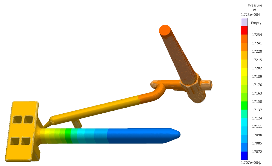
Design for Manufacturing, DFM, is a part of the design process and not necessarily a design decision. However, it is a crucial part of the design process and must be discussed. OEMs must take the results from DFM studies and simulations seriously! These provide designers and OEMs with important information and allow a better understanding of how production can be optimized. For more information, watch the video!
This is why it is imperative for OEMs to partner with an injection molder, such as Crescent Industries, who has Design for Manufacturability (DFM) expertise; this simply means the tool design and manufacturing teams are integrated to allow manufacturability issues to be identified and addressed during the design process instead of after the tool is fabricated – saving OEMs significant product development time and cost!
Crescent has been manufacturing injection molded components for over 75 years and has a rigorous process for designing parts that meet our customer’s specific needs and address all of the design concerns noted above – in fact, click here to receive our mold design guidelines that cover many of these topics. Partner with a company that is on the leading edge of manufacturing technology and continues to reinvest profits into the company’s capabilities.

