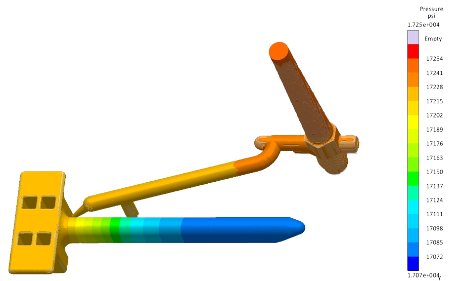
Using Mold Flow Simulation for Injection Molded Parts
If you’re designing a plastic part, there are a lot of considerations to think about from a manufacturability standpoint. Having Mold Flow simulation software watching your back ensures your original design has the best practices in mind. From simple flow simulations to complex quality predicting, warp analysis, fill analysis, weld lines, pressure, temperature, and gate location, utilizing some type of mold flow simulation will save you a lot of time in your product development process.
If you don’t have a simulation license there are plenty of injection molding suppliers that make this part of their normal DFM process, like Crescent Industries. Mold flow simulation has been around for a long time and at this point it should be a standard process for any injection molding supplier, however, most injection molders aren’t willing to dedicate the financial resources.
Below is a review of a previous project that Crescent Industries completed and a few of the highlighted areas of the mold flow simulation report.
Part Fill
Once you begin injection of the part, the material will flow in the path of least resistance, gate location, and style will play a role in exactly how the part fills and where the end of the fill is located. Throughout this part fill simulation process, you can get an idea of potential areas of concern with the fill and think about the design changes needed.
This information can also be very useful as a training tool for some of the new employees or people in other departments who don’t typically have much involvement in design or process. By either viewing the fill sequence on 2 different parts below or watching an animated video, you can fully understand how the part is filled with plastic.


Shear Rate
In injection molding, shear occurs when layers of molten resin flow relative to each other. How fast shear occurs is referred to as the shear rate. Shear rates are important to the design and molding of plastic products. As shear rates rise, the molecular chains that make up the polymer are stressed more. If the shear rate is too high, this can reduce the mechanical properties of a product and the material may start to lose its physical properties.
Each material has a critical shear rate that it is rated to withstand. It is suggested by most material manufacturers to stay under that critical rate. Typically, the highest amount of shear occurs in the gate at the beginning of the part filling phase.
In the image below, we can view the shear rate to determine if there are areas that will drastically affect the quality or processing of the plastic part.

Air Entrapment
One of the top causes of cosmetic rejects in molded parts is air entrapment causing bubbles or voids. Air entrapment is when two separate flow fronts join around a pocket of air during filling. This troublesome part defect not only results in appearance problems but impairs physical properties as well. This is a common occurrence and is often difficult to resolve in the production phase.
Regardless of size, air entrapment can cause problems in venting, and result in burn marks in a part. Small areas of air entrapment can typically be resolved with venting in the mold, but larger air entrapment is more difficult.
By viewing the image below, we can determine that based on the current conditions there is an area of concern that would not have been realized in pre-production without the Mold Flow simulation.

Solidified Material
In this injection molding cycle the part will experience both melt and solid stages. In order for an injection press to pack the mold cavity with the optimal amount of material around inserts, material in the melt stage is best in those areas.
Regions in blue in the below images will show areas where material will become solid, and optimal material may not pack into those areas.


Weld Lines
Weld lines occur when two different flow fronts of material form together during the filling of a part. Weld lines, depending on the conditions can become strong welds or weak welds. Sigmasoft measures this in severity as “1” being the strongest weld. Weld lines are typically considered strong if the material is pressurized, and the temperature is still in the melt stage while the weld is occurring.


Pressure Around Inserts
The next images show how pressure builds around the insert during the filling of the cavity. As mentioned in previous slides pressure is an important factor to keep track of when determining if a weld is strong.
Pressure at 100% fill around the inserts will be used to determine the strength of the weld.
Pressure at 10% of fill

Pressure at 50% of fill

Pressure at 100% of fill

Melted Material Chart
On the below melted material chart, it’ll be shown to determine if the material around the inserts is in the melt stage during 100% fill. If the material is still in the melt stage, there is an optimal situation for the material to pack around the inserts. The pressure and temperature noted from the simulation will be plotted right to the (black) diagonal line if the material is in the melt stage.
- Pressure around inserts at 100% fill:
- 15,000 PSI = 1035 Bar = green line in chart
- Temperature around Inserts at 100% fill:
- Angle 1: 490 F = 254 C
- Angle 2: 380 F = 193 C
- Average: 223 C (Plotted on the X-Axis, following the green line)

Summary and Observations
The part seems to fill well and develop strong weld lines. The placement of the gate is in an area that promotes high enough temperature and pressure to pack well around the inserts of the part. A problem area could be packing out the ribs on the underside of the part.
- Shear Rate: Shear rate is well under the critical shear rate for PC/ABS (45,000 1/s).
- Solidified Material: The material that becomes solidified seems to be mostly in the ribbed section under the part. There is not much solidified material around the inserts, which generally leads to snug inserts that have plastic packed around them with high pressure.
- Weld Lines: The Weld lines in the part form with strength. The severity rating on critical weld lines shows to be close to 1, which is optimal.
- Temperature: The temperature of the material around the inserts is high enough during filling to support the packing of material around the inserts.
- Pressure: The pressure of the material around the inserts is high enough during filling to support the packing of material around the inserts.
While some reports are simple and straight forward confirming the design is ready for molding, other reports can be horrifying to design engineers. Regardless of how much experience a designer engineer or injection molding supplier has, it’s always a good idea to run a mold flow simulation as part of the upfront design for manufacturability (DFM) process. This will increase the confidence prior to tool design and also allow opportunities for minor to complex design changes to improve and have a more efficient production part.
Check out our website, If you’re interested in learning more about how Crescent Industries.
Related Articles
-
Apr 10, 2025
How Are Injection Molds Made for Plastic Manufacturing?
Read MoreDo you have a part design and need an injection mold built? Are you interested in finding a tooling...
-
Mar 19, 2025
Top 6 Advantages of Injection Molding for Your Project
Read MoreInjection molding — the process of injecting molten resin into a mold — is one of the most...
-
Mar 17, 2025
Labware & Diagnostic Injection Mold Building and Molding
Read MoreMedical device molding requires much higher levels of precision injection molding and tolerance...

