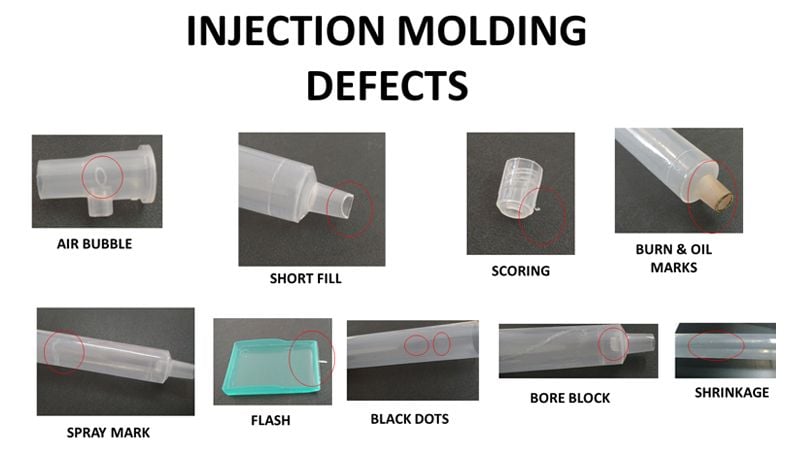
Top 5 Most Common Quality Defects in Injection Molding
Plastic injection molding is a very cost-effective method for mass production of parts – but even the best designs sometimes have shortcomings that result in quality defects. It is important to be familiar with these defects in order to identify and trouble-shoot them, as well as avoid them by developing a competent design! Below are the top 5 most common quality defects in injection molding and how each can be resolved. Additionally, for more information on these and other types of cosmetic defects see the glossary that was compiled by The Society of Plastics Industry.
1. Flash
Flash is a thin layer of plastic that flows outside of the cavity, typically where the two halves of the injection mold meet. Flash can appear on the part’s edge along the parting line of the mold. It can also occur at ejector pin locations and anyplace where the mold has metal meeting metal to form the boundary of the part.
Flash cools and remains attached to the final product. Injection molders must remove unwanted flash by a process called deflashing which may involve operations personnel or robots trimming the excess material in between cycles. The presence of flash usually results in a longer, more labor-intensive process, lower product quality, and ultimately damage to the mold – all leading to higher costs! For these reasons, the root cause of flash issues needs to be identified and resolved. Below are some causes and remedies for flash.
- Flash occurs when the mold cavity halves are not held together with enough pressure; thus, one remedy is to increase the clamp force.
- Flash may occur if the material is too fluid. Consider decreasing the operating temperature to achieve the desired material flow.
- Flash may be the result of trapped gases inhibiting the material flowing freely; ensure there is adequate gas venting.
- Flash may be caused by poorly fitting, or designed, mold plates; inspect the mold and make any necessary repairs or replacements.
2. Weld Lines
A weld line refers to a line, notch or color change that is created on the molded part caused by the convergence of two separate flows of molten plastic. This occurs wherever there is a hole, notch, or any other feature on a part which divides the flow of plastic into 2 separate “flow fronts.” As these flow fronts come together on the other side of a given feature, the molten plastic rejoins or “welds” together and often forms a slight line on the part, similar to a parting line mark. At the spot where the two flows rejoin there is inadequate interfusing of the plastic – perhaps because there is already partial cooling and then re-solidification of the plastic at this point, or perhaps on a molecular level the molecules are not oriented in the same direction of the flow path. In any case, the result is a weld line and in some cases a reduction in strength.
Below are some options that may resolve or move weld lines to a more desirable location for improved aesthetic or strength reasons; however, OEMs should work with their manufacturing partner before implementing these steps to ensure solving a weld line issue does not create a different problem.
- Increase the temperature of the mold or plastic material in order for the two flow fronts to interfuse better.
- The gate location influences where the weld line is on the part. Change the gate positions before the mold is fabricated in order to inject the material at more ideal locations and have weld lines in a more preferable location.
- Changing the product wall thicknesses will result in a different fill time, and may cause the flow fronts to meet at a different spot and move the weld line location.
- Adjust the design to be a single source flow to avoid the issue caused by two or more flow fronts, or use a raw material with a lower viscosity to improve flow conditions.
- Increase the injection speed in order to fill the mold more quickly and ensure the material does not prematurely cool down; in addition, when the speed is adjusted the flow fronts may meet at a different spot and move the weld line location.
For more information on the Factors Affecting the Injection Molding Process
3. Sink Marks
A sink mark is a local depression on the surface of a part. These marks are typically found in thicker areas due to varying cooling rates across the part or insufficient cooling while the part is in the mold. They can also be caused by low pressure in the cavity or an excessive temperature at the gate.
To resolve sink marks, the mold temperature can be lowered, the holding pressure raised, or holding time prolonged to encourage more adequate and even cooling. Additionally, adjusting the part design to reduce the thickness of thick wall sections will also promote quicker cooling and reduce the probability of sink marks.
4. Short Shots
A short shot is an incomplete part where the molten plastic does not fill the entire mold cavity, resulting in a portion where there is no plastic. An example of a short shot is a missing prong on a plastic fork. There are various reasons, and remedies, for short shots:
- Short shots may be caused by the use of a raw material that is too viscous and is, therefore, unable to flow into all sections of the mold cavity. If this is the case, use a less viscous resin that provides a better flow rate.
- Short shots may be the result of improper or inadequate venting, resulting in a pressure buildup that inhibits flow. Consider adding more venting near the area of the mold that is having short shot issues.
- The void in the cavity may be because the material is unable to flow into the cavity. If so, raise the mold temperature to allow the plastic to flow into the hard to reach areas of the mold.
- Material flow may be restricted due to frozen flow channels. The channels may need to be cleared to permit the desired flow that fills the entire mold cavity.
- Short shots may be related to the fill rate during injection; if so, increase the injection pressure and/or speed.
5. Burn Marks
A common defect in injection molding is burn marks. These are discolorations on the part surface that are often a dark black or red color. These marks are where the plastic material overheated and literally burned against the injection mold.
Burn marks are most often caused by the following: excessive injection speed or undersized gating that does not permit proper gas venting, excessive temperature that degrades the resin, or leftover material from a prior cycle that overheats. Burn marks can be addressed by reducing the cycle time, temperature, and/or injection speed. If burn marks are due to inadequate venting, additional vents can be added or gates can be resized to ensure a proper thickness that does not cause material degradation. Lastly, the system should be properly cleaned between cycles to ensure no material is left behind that may result in burn marks for the next batch.
Why Crescent is your “Go-To” Partner
In many cases, predicting potential defect issues is achieved using computer simulations. Engineers at Crescent Industries are able to help perform these simulations and are ready to help with advice and suggestions for your next injection molded plastic component or device.
Additionally, like most optimization challenges in manufacturing, creating the best design requires close collaboration between OEMs and their molding partner. It is imperative for OEMs to partner with an injection molder, such as Crescent, who has Design for Manufacturability (DFM) expertise; this means the tool design and manufacturing teams are integrated to allow manufacturability issues, such as quality defects, to be identified and addressed during the design process instead of after the tool is fabricated – saving OEMs significant product development time and cost!
Contact us today to learn how we can help with your next injection molding project.
Related Articles
-
Mar 19, 2025
Top 6 Advantages of Injection Molding for Your Project
Read MoreInjection molding — the process of injecting molten resin into a mold — is one of the most...
-
Mar 17, 2025
Labware & Diagnostic Injection Mold Building and Molding
Read MoreMedical device molding requires much higher levels of precision injection molding and tolerance...
-
Feb 19, 2025
Injection Molding vs CNC Machining: Which Method to Choose?
Read MoreEvery year, humans produce and use countless plastic products in various shapes, sizes, and...

